sheet metal drawing standards
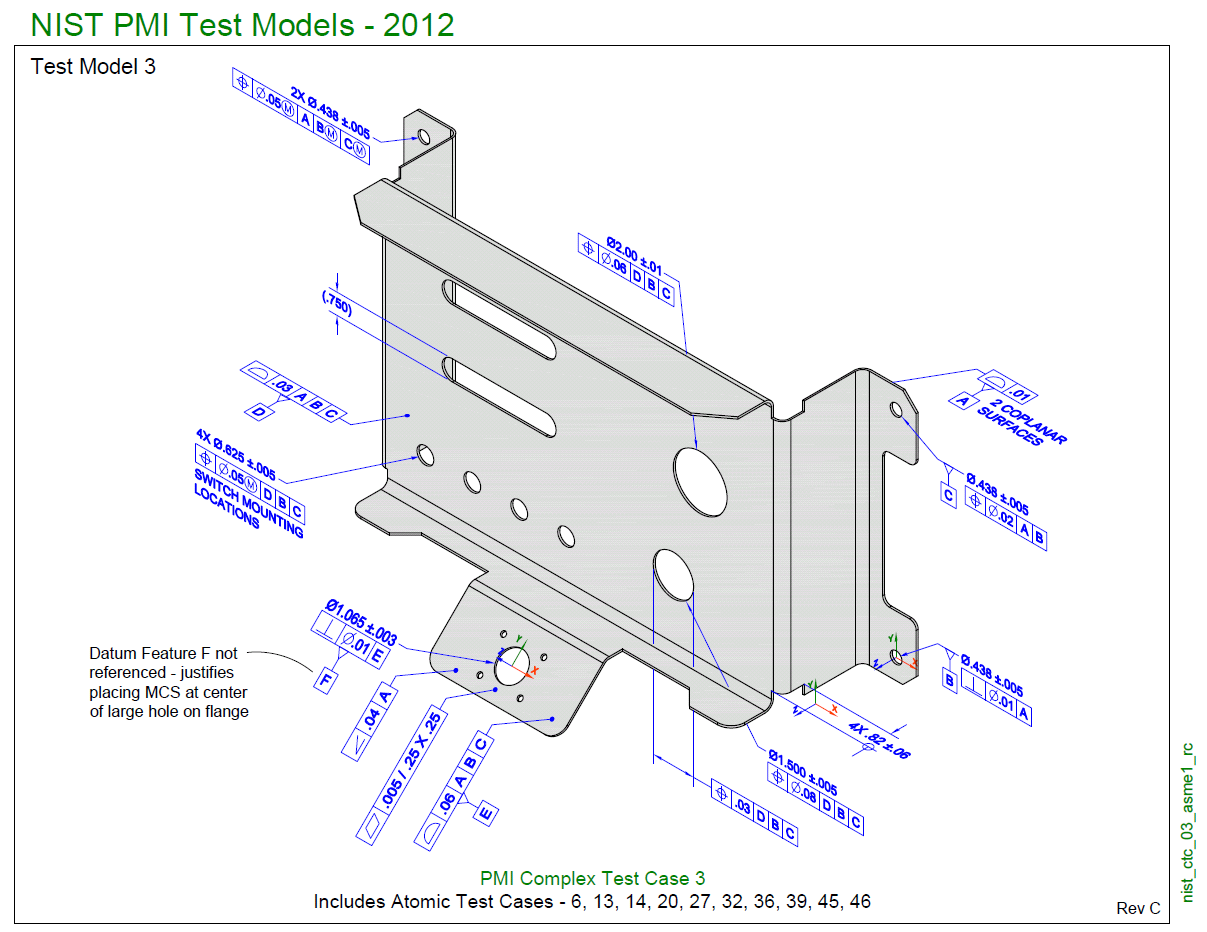
2015 and AS 9102. Fig 1Pictorial Representation of Anvil.
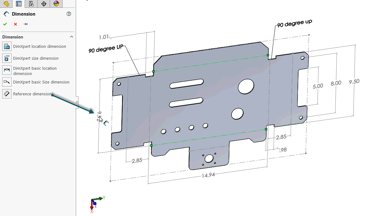
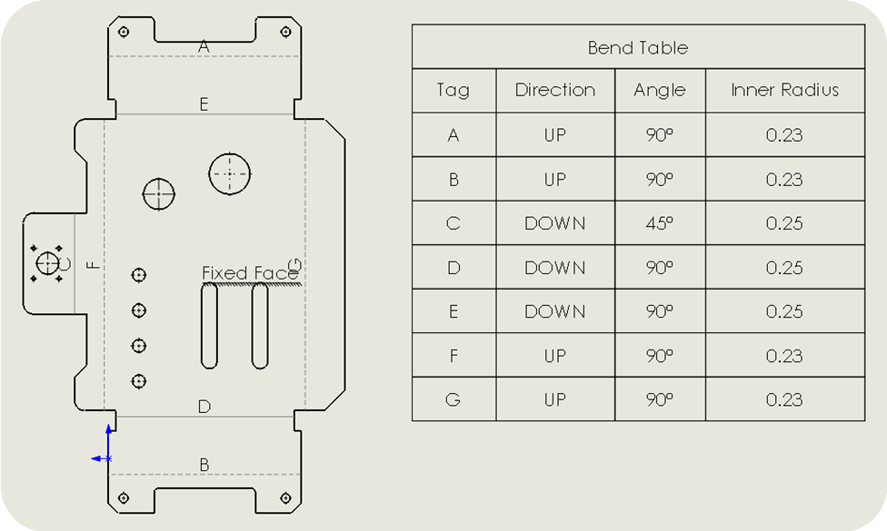
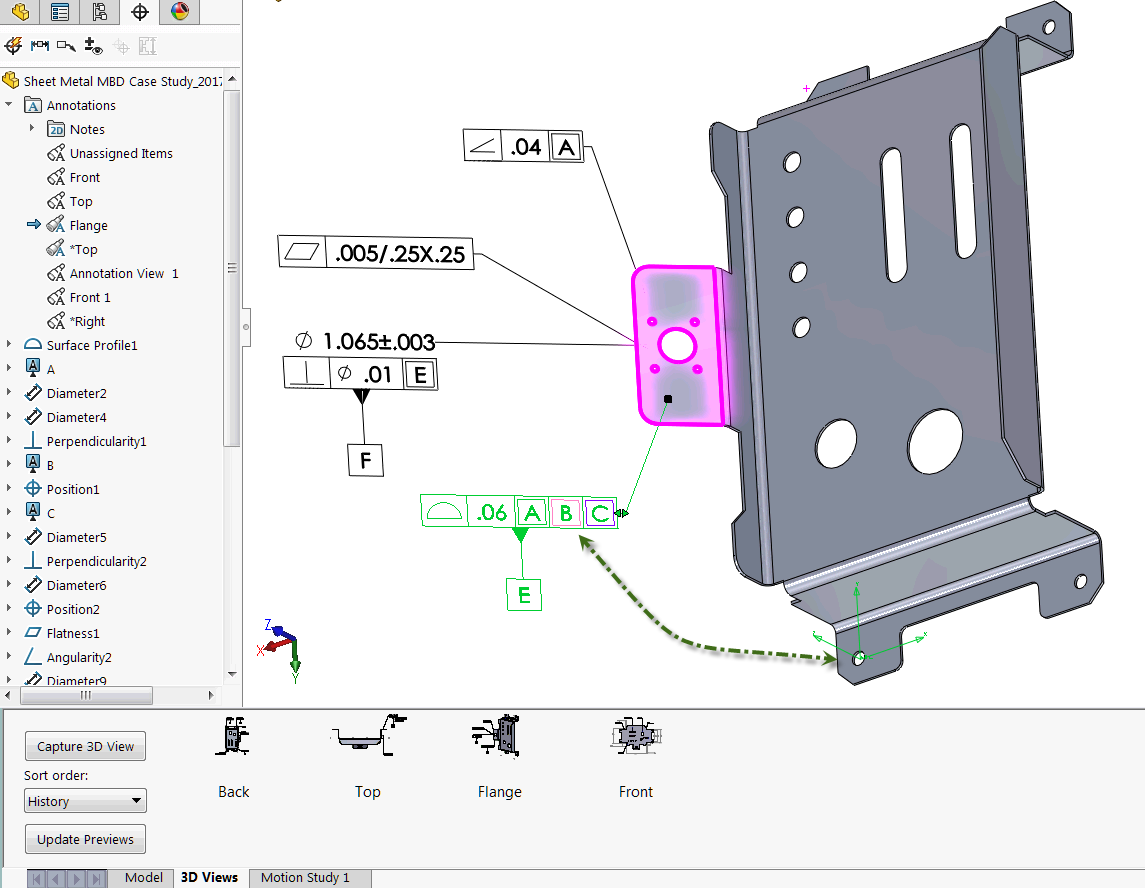
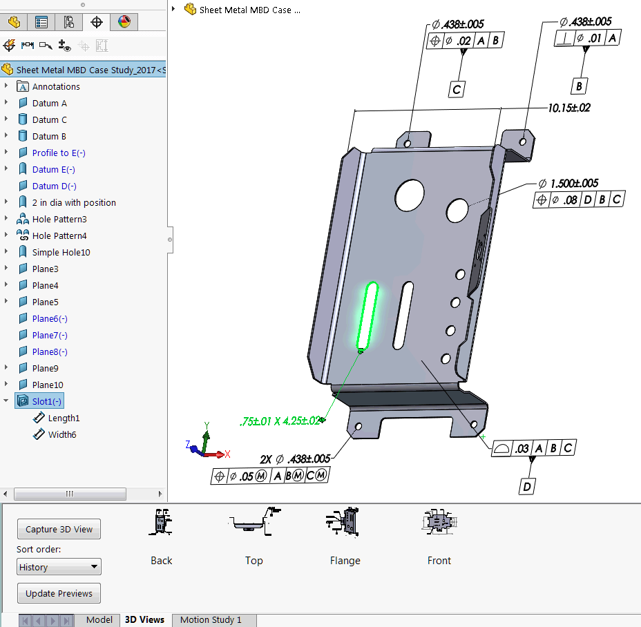
How To Define The Mbd Data Of Sheet Metal Parts Engineers Rule
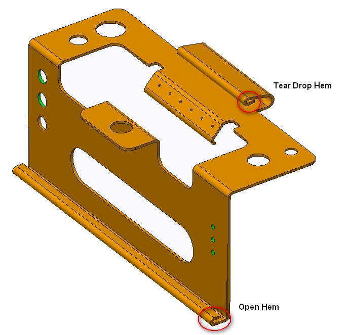
However overall tolerances will depend on the radius sheet thickness and any other features near the hem.
. Radii not be less than the thickness of the sheet T. Lower-left corner of the drawing sheet touching the left and bottom border lines 3. Upper-left corner of the drawing sheet touching the top and left border lines 2.
Minimum Sheet Metal Flange Bend Length 3 x Sheet Thickness Bend Radius. Why ISO Matters in Custom Metal Fabrication 1. Millimetres Mils Gauge.
By this is meant that the materials dealt with are usually in the form. Narrow Your Results Revision. Most-Recent Revision Only 116 Not False 0 Publisher.
Institute of engineering and management logo. I am not aware of standards for them separate from any other kind of fabrication drawing. Access to company-defined standards tables Dedicated drawing capability including unfolded view.
REQUIREMENTS FOR SHEET METAL PART DRAWINGS Sheet metal parts are typically created from material less than 250 inches thick and are formed by folding the material at specific locations with a controlled bend radius. 3D CAD files are converted into machine code which controls a machine to precisely cut and form the sheets into the final part. Above the title block touching the right border line and the title block 4.
Sheet metal parts are known for their durability which makes them great for end use applications. Sheet Metal Fabrication is the process of forming parts from a metal sheet by punching cutting stamping and bending. This video demonstrates how to properly dimension a sheet metal layout technical drawing.
BENDS Minimum inside diameter on a hem should be 4X the thickness of the sheet. 215 On detail drawings with 3 or more hole sizes holes shall be tabulated using the label shown. Sheet metal is any metal that has a thickness in between 056 millimetres.
The minimum recommended sheet metal flange bend length avoid cracks in the bending area. See document 10-0005 Blah Drawing Drafting Standards and Practices for the proper setup of a sheet metal drawing. ASTM 3 SMACNA 6 MPIF 11 ICBO 1.
The symbols for the location of pipes in a building are as follows. If your order requires exact duplication of materials shapes and cut ISO standards help make that happen. To the left of the title block touching the bottom border line and the title block.
216 For slots callouts for CENT TYP and RADIUS or R are assumed. Form height to thickness ratio To determine the minimum form height for sheet metal use the following formula. Extracting Drawings from the Sheet Metal Part Basic Tasks Managing the Default Parameters Editing the Sheet and Tool Parameters Modifying the Bend Extremities.
9981870 - Drawing Compounds Water Based for Sheet Metal. 214 All tapped holes are assumed to have coarse threads unless otherwise specified. I assume they are pretty good.
There are other measurement units used to categorise metals by thickness though. Drawing upon the considerable experience of its own CADD Task Force. Your tolerances to and from bends should reflect this.
Institute of engineering and technology. Foils sheets and plates are pretty much the same with the only difference being in thickness. A description is not available for this item.
Most-Recent Revision Only Clear all. Sheet metal shops can bend to tolerances of 015 or 04mm. When pipes and their relative components are shown on a drawing it is vitally important that the craftsperson can correctly identify their locations and positions.
Institute of engineering and technology davv. Institute of engineering and technology logo. I do lots of sheet metal drawings.
D 25T R see below The height can be less but it required secondary operations and is far more costly. Sheet Metal Roof Coverings. Sheet Metal Drafting Standards 1-20 of 116 results 20 results per page 10 results per page 30 results per page 50 results per page 100 results per page Filters.
SCS articulates the CAD standards that will enable SMACNA members and the rest of the AEC community to apply CAD effectively to mechanical fire protection and plumbing design and construction. ISO 2768-1 is intended to simplify drawing indications and specifies general tolerances in 4 tolerance classes f fine m medium c coarse v very coarse. Bevel and Hypoid Gears ASME B4612002 Surface Texture Surface Roughness Waviness and Lay ASME SI-11982 ASME Orientation and Guide for use of SI-1 Metric Units - Ninth Edition.
Yeah I have that but I just feel that a few different rules apply in sheet metal so I was trying to get a little better insight on how to detail sheet metal parts vs machined parts. January 1 2020 - GMNA. Standard in which case AS SHOWN should be noted on the drawing.
This specification details the requirements for water based drawing compounds that provide additional lubricity to aid in metal forming operations and must be compatible with current production. But what makes these guidelines so beneficial to customers like you. The feeders also needed frequent mainte- nance and replacement of items such as bearings and chains.
Sheet metal drafting is merely the application of the principles of ordinary mechanical drawing to objects which for the purposes of drawing lack thickness. HEMS Overall all bend radii in osets should be 0030. For Spur Helical Double Helical and Rack ANSI Y1472-1978 Gear and Spline Drawing Standards Part 2.
Im pretty sure there isnt one either but figured Id try. Many sheet metal workers are educated and certified in two popular standards --ISO 9001. Straight-sided sheet metal container served as the feeder hopper and a screw at the hoppers bottom fed material.
It applies for the linear dimensions and angular dimensions such as external sizes internal sizes step sizes. Institute of engineering and technology hyderabad. ANSI Y1471-1971 Gear Drawing Standards Part 1.
I have never checked the accuracy of the punching or laser cutting or whatever. However fabricating the feeders was ex- pensive and a local fabricator had to CUS- tom-make the feed screws. Institute of engineering and technology iet lucknow uttar pradesh.
It shall be equal to three times of sheet thickness plus bend radius. Sheet Metal Drawing Standards - 17 images - portal frame dwg section for autocad designs cad ceramic tile t bar transition strip ceramic tool company structural steel detailing invetive in melbourne we space truss steel structure dwg detail for autocad. It reviews general dimension standards as well as requirements for.
Sheet metal is one of the shapes and forms metal can be bought in.
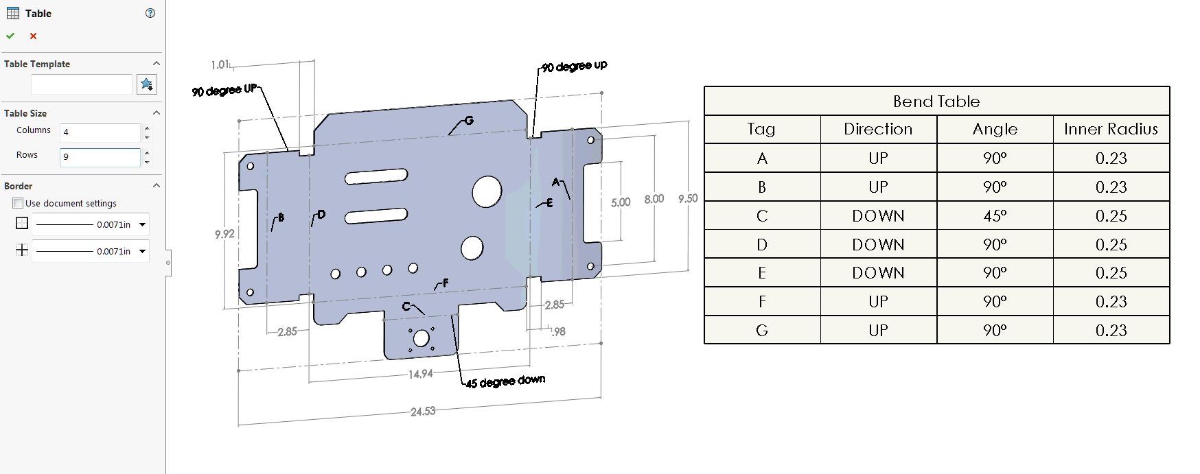
How To Define The Mbd Data Of Sheet Metal Parts Engineers Rule
How To Define The Mbd Data Of Sheet Metal Parts Engineers Rule
How To Define The Mbd Data Of Sheet Metal Parts Engineers Rule
How To Prepare A Perfect Technical Drawing Xometry Europe
How To Prepare A Perfect Technical Drawing Xometry Europe

Solidworks Sheet Metal Drawing Tutorial Bend Line Flat Pattern Unfolded Bend Table Punch Table Youtube

Fusion 360 Help Sheet Metal Flat Patterns Autodesk
Design Tips For Sheet Metal Bend Relief Small Holes Hole Distortion Near Bends And Minimum Flange Widths
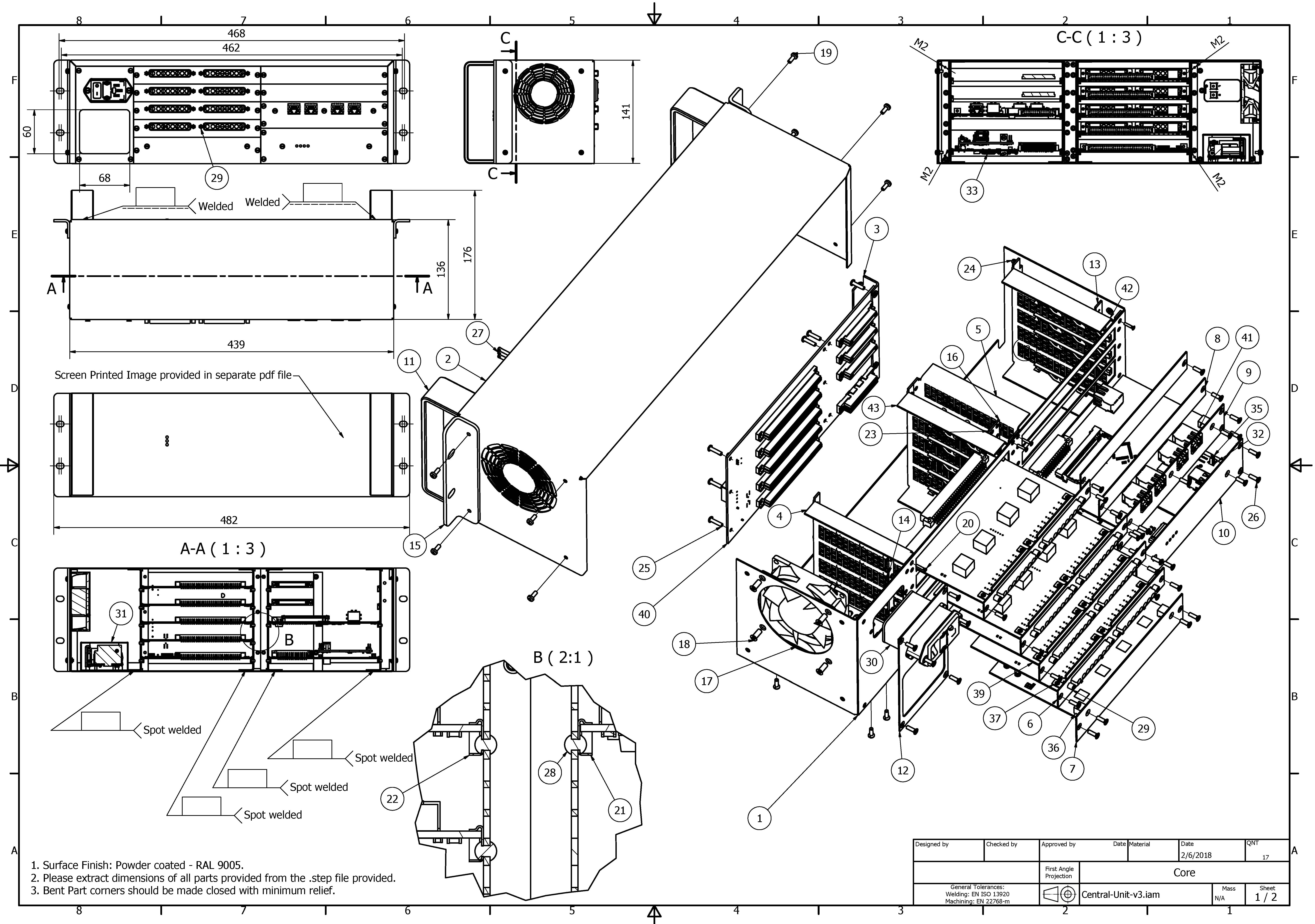
Freelance Sheet Metal Design Services For Companies Cad Crowd
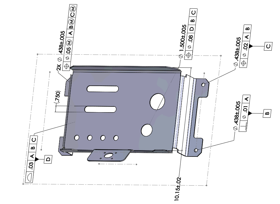
How To Present The Mbd Data Of Sheet Metal Parts Engineers Rule
Freelance Sheet Metal Design Services For Companies Cad Crowd
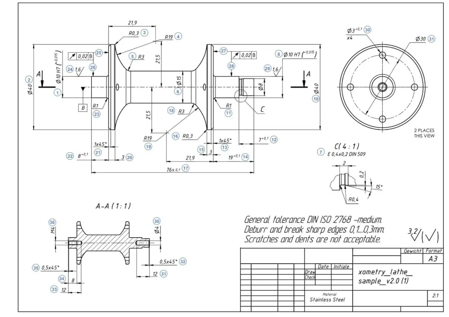
How To Prepare A Perfect Technical Drawing Xometry Europe

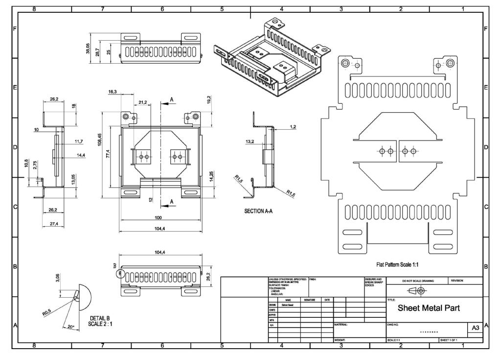
Sheet Metal Dimensional Drawing Example Vista Industrial Products Inc
How To Define The Mbd Data Of Sheet Metal Parts Engineers Rule
How To Define The Mbd Data Of Sheet Metal Parts Engineers Rule

Pin On Solid Draw

Sheet Metal Drawing Sheet Sheet Metal Drawing Drawing Sheet Sheet Metal
Sheet Metal Design Guidelines Dfmpro

Sheet Metal Dimensional Drawing Example Vista Industrial Products Inc